EVK Pinout and Jumper Settings
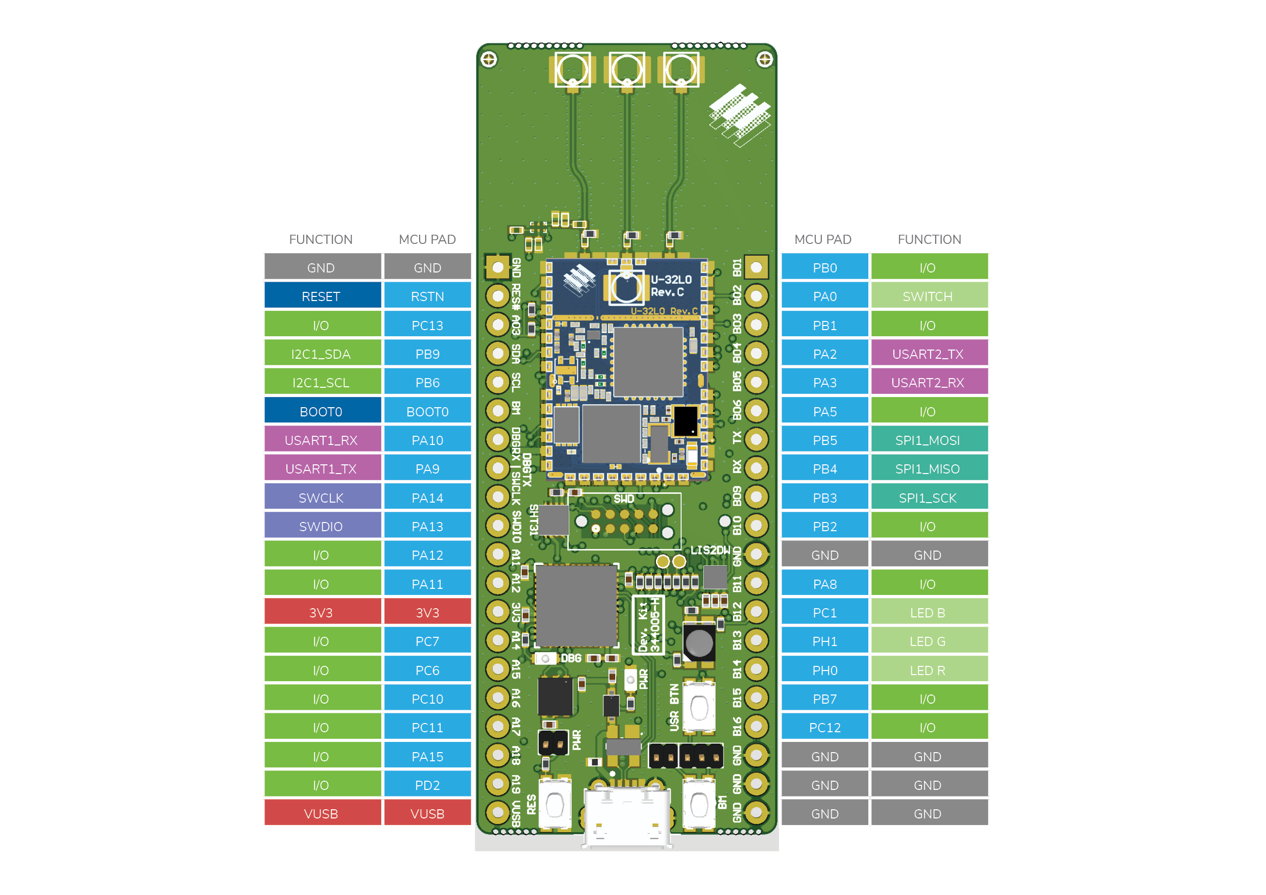
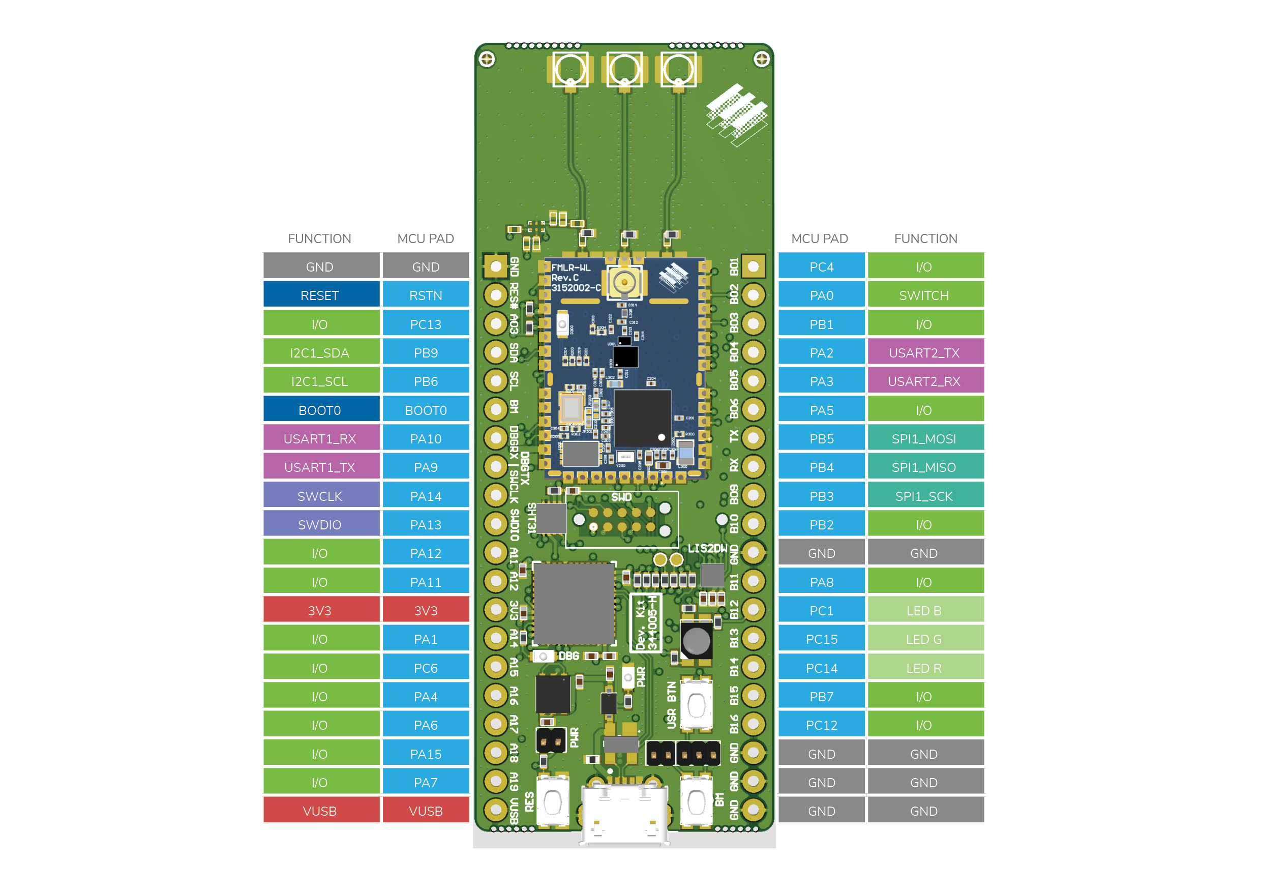
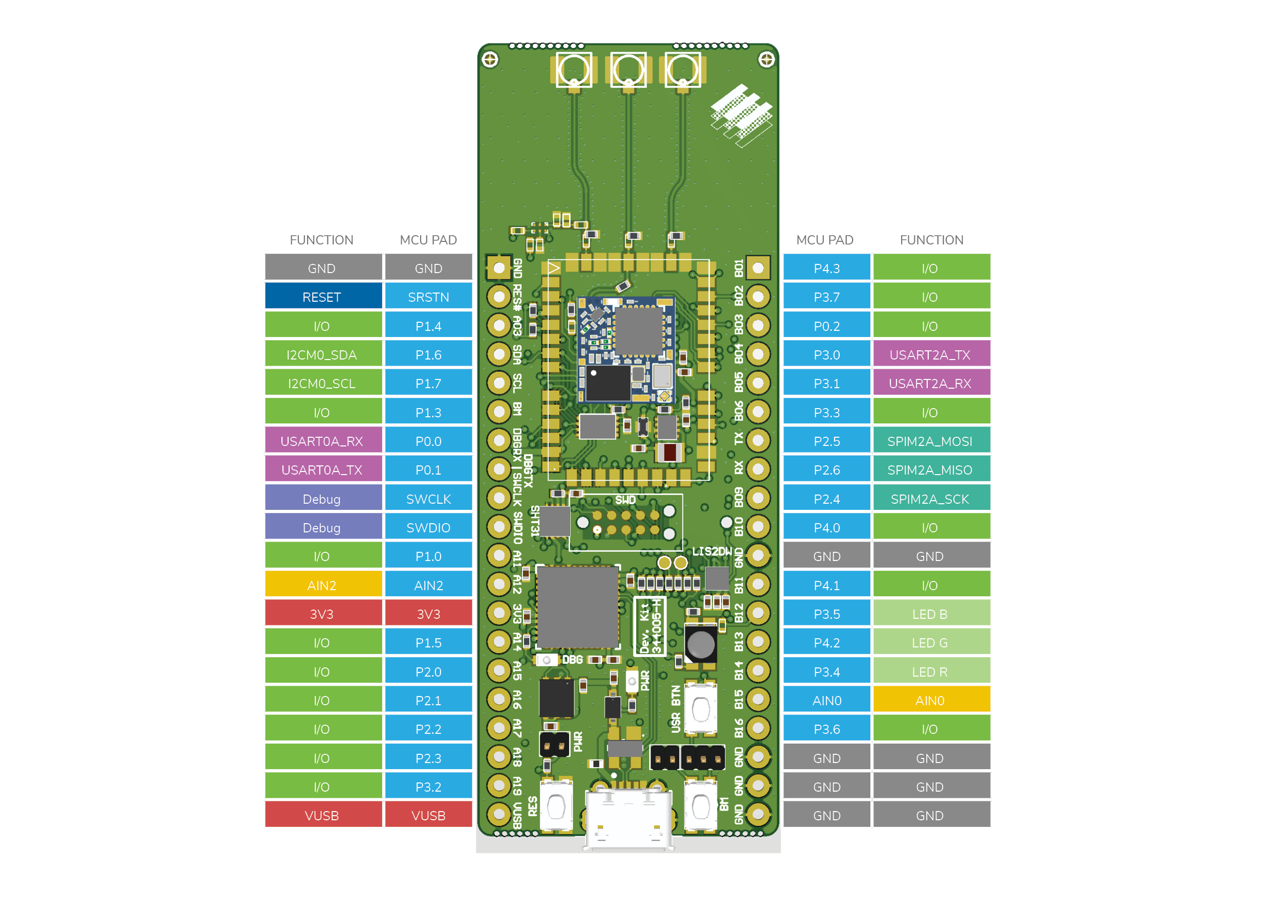
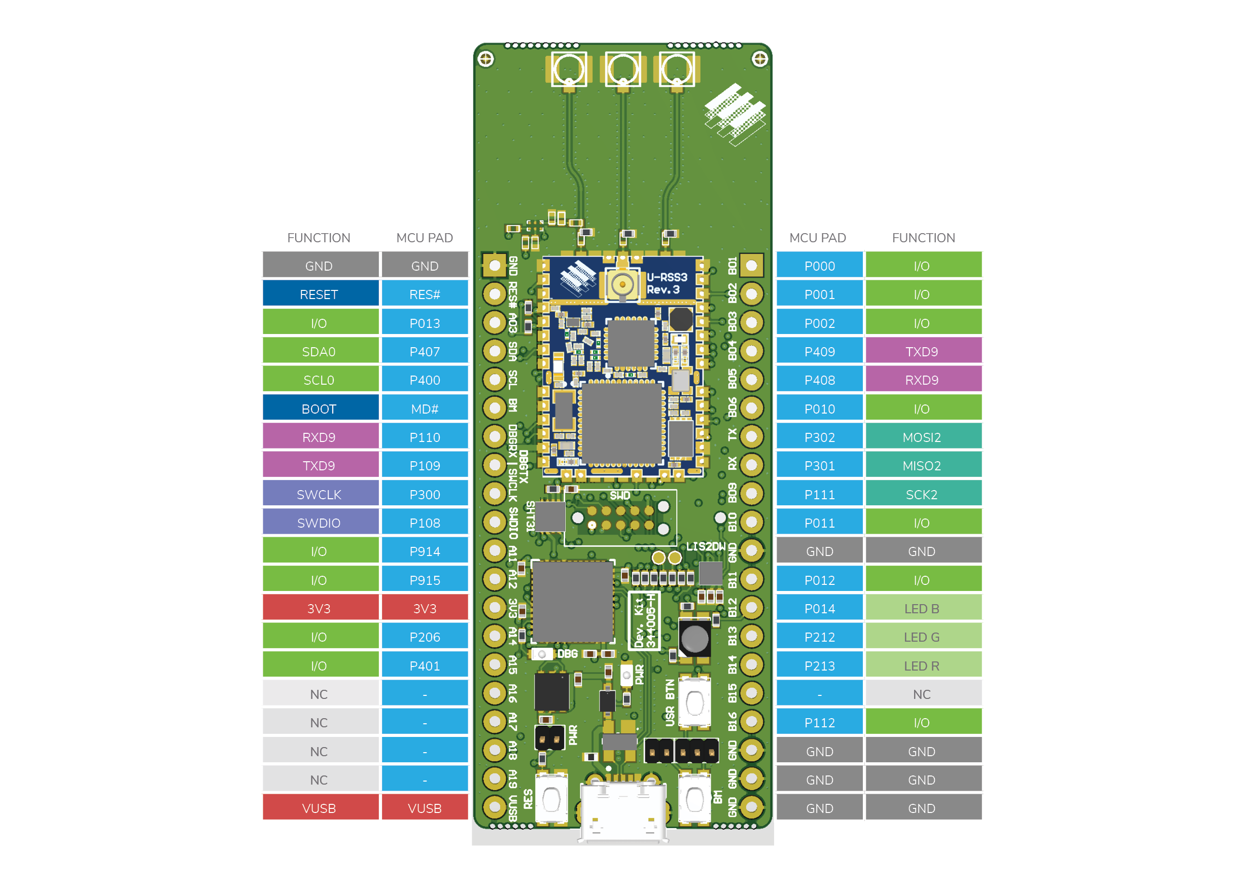
Breakout board pin out
All evaluation kits are based on the same carrier board. The main pin mapping such as power and ground is identical for all EVK. All main communication interfaces are also routed for maximum compatibility.
MCU pin naming and pin mapping are different for each EVK.
Download all EVK pinouts as PDF.
Note
Older revisions of EVKs (< rev 7/H) do not feature on-board J-Link programmer and accelerometer. They are shipped with J-Link mini programmer. The EVK pinout remains the same.
EVK Configuration / Jumpers
There are three jumpers (JP1, JP2 and JP3) on the EVK for configuration. JP1 and JP2 are used to configure the EVK board for the assembled module type.

| Module | JP1 | JP2 |
|---|---|---|
| FMLR-72-STM | Hi (Pin 2-3) | open |
| FMLR-61-REN | Hi (Pin 1-2) | closed |
| FMLR-61-MAX | Lo (Pin 2-3) | - |
| FMLR-80-STM | Hi (Pin 2-3) | open |
| FMLR-61-STM | Hi (Pin 2-3) | open |
| FMLR-1110-ST | Hi (Pin 2-3) | open |
| FMLR-WL-STM | Hi (Pin 2-3) | open |
JP3 can be used to disconnect the module from the USB power supply for low power development and current measurement. If JP3 is not mounted, power the system through 3V3 pin on the interface.